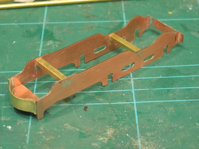
The space between the frames being about 21 mm giving plenty of room for a decent sized motor and gears.
The main frame spacers were cut from some 4x4mm square tube with a 1/16th inch diameter brass tube through the middle, the round tube being soldered into the frames.
at the front another piece of copper clad PCB cut and filed to shape forms the frame spacer and "shelf" for the tool box. A piece of 1/4in wide brass bent to shape by eye forms the distinctly shaped front "Buffer beam" Like wise at the back,another piece of copper clad forms the stretcher under the front of the firebox and the extension frames will be attached to this.

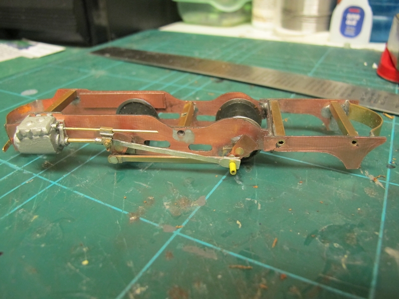
The wheels are Alan Gibson 16mm Bullied tender wheels for 4mm scale.
I made the axles from 1/8th brass tube with 3/32in Tube for the crank extensions.
The cranks shown here are Markits 4mm scale items which I didn't use.
I will be using the home made ones seen in my last blog entry.
Also shown is a Alan Gibson 38:1 self contained gearbox. Again I did not use this item as for some reason it has a tight spot and tends to stick once every revolution. I'll sort that out and use it in another project.
The left hand cylinder/ slidevalve assembly made up and fitted, and the single slide bar cross head and conrod fitted for testing.
The cylinder was made up from various bits and pieces including Glass fibre tube, PVC and brass tubes and a lot of cutting and filing!
The cross head is a modified Comet models 4mm scale item. the conrod was fabricated from the scraps of Nickel silver etch in a similar manner to the connecting rods seen in my last entry.
Note also that the rear frame extensions have been cut, shaped and soldered on to the main frames with the rear drawbar cut, bent to shape by eye again, and also soldered into position.

The wheels and axles can be seen as well as the gear sprocket.
Note that the centre spacer is slightly angled to allow the motor to sit properly and the worm engage the gear correctly.
Although not shown on any of the pictures I have had the motor fitted and the chassis running to check all is OK.
I can happily say that all runs fine so far.
The motor has been removed again so that the right hand side cylinder and conrod can be made and fitted. After that comes the Walschearts valve gear!
That's the progress to date, hope to post more soon.
Cheers!
Frank
No comments:
Post a Comment